Tel:400 821 7118
Fax:021 6291 7119
E-mail:info@sipworks.com.cn
"What if?" This is the inspiration that drives innovation, using SOLIDWORKS ® Flow Simulation software allows you to eliminate risks and replace them with a 3D workspace that can virtually test new ideas, develop new designs, and help push products to market faster.
Implementing wiser designs through parallel engineering
SOLIDWORKS Flow Simulation allows product engineers to access powerful CFD (Computational Fluid Dynamics) capabilities, helping them accelerate product innovation. This extension technology utilizes the familiar SOLIDWORKS 3D CAD environment to not only ensure the operation of your product, but also to understand how the product works in the actual environment.
Intuitive and powerful CFD simulation for product engineers
Specially designed to tackle CFD engineering challenges, SOLIDWORKS Flow Simulation enables engineers to fully utilize CAD integration, advanced geometry meshing capabilities, powerful built-in convergence, and automatic flow pattern determination without sacrificing ease of use or accuracy.
With the powerful capabilities of SOLIDWORKS Flow Simulation, product engineers and CFD experts can predict flow fields, mixing processes, and heat conduction. They can also directly determine pressure differences, comfort parameters, fluid forces, and fluid structure interactions during design. SOLIDWORKS Flow Simulation enables true CFD without the need for advanced CFD expertise.
SOLIDWORKS Flow Simulation software eliminates the complexity of fluid analysis, allowing engineers to easily simulate fluid flow, heat conduction, and fluid forces, thereby studying the impact of fluids or gases on product performance.

Evaluate and optimize complex flows
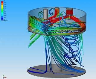
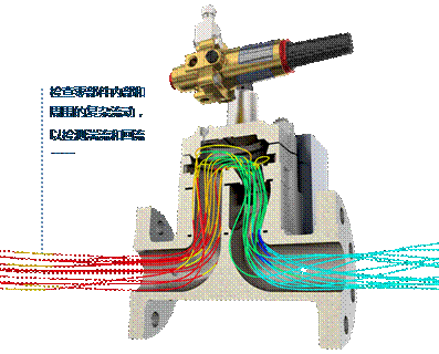
Check the complex flow inside and outside components through parameter analysis
Align your model with flow conditions (such as pressure difference) to meet design goals
Detecting turbulence and backflow issues through the flow trajectory of animations
Understanding the flow of non Newtonian fluids such as blood and liquid plastics
Evaluate the impact of different impellers and fans in the design
Including complex effects such as pores, cavities, and humidity
Reduce the risk of overheating in design
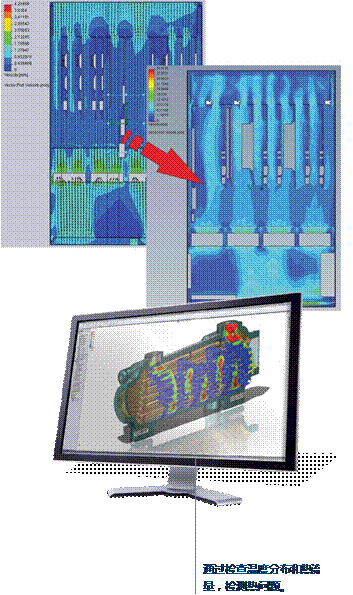
Display and understand the temperature distribution inside and around the product
Combining flow and thermal analysis to simulate convection, conduction, and radiation effects
Simulating advanced radiation and wavelength dependent radiation characteristics with semi transparent materials using HVAC modules
Applying boundary conditions and heat sources related to time and coordinates
Find the optimal size that meets the design goals, such as heat exchanger efficiency
Obtain heat source and PCB layer definition from EDA thermal properties

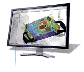
Optimize the thermal performance of PCBs and electronic components
You can use SOLIDWORKS Flow Simulation and electronic cooling modules to perform component thermal analysis on designs using printed circuit boards (PCBs) and electronic products.
In addition to the core SOLIDWORKS Flow Simulation model, the electronic cooling module also adopts a complete set of intelligent models, which can quickly and accurately establish a wide range of electronic cooling applications. The models that use electronic thermal simulation include:
Fan
Thermal electric cooler (TEC)
Radiator simulation
Dual thermal resistance component model (JEDEC standard)
Simplified model of heat transfer tube
PCB generator tool
Electrical contact conditions
Joule heating calculation
Extensive electronic model library

Predicting and implementing airflow and comfort parameters in work and living environments
You can use SOLIDWORKS Flow Simulation and HVAC application module's thermal comfort factor analysis to understand and evaluate the thermal comfort of multiple environments. Evaluating the thermal environment of the workspace requires knowledge of comfort parameters and providing information on air quality and factors calculated using HVAC modules, including:
Predicting average thermal sensation index (PMV)
Predict the percentage of dissatisfied individuals (PPD)
working temperature
Exhaust temperature
Air Distribution Characteristics Index (ADPI)
Pollutant Discharge Efficiency (CRE)
Local Air Quality Index (LAQ)

Use powerful and intuitive result visualization tools to gain valuable insights
Using profile and surface diagrams to study the distribution of result values, including velocity, pressure, vortices, temperature, and mass ratio
Comparing fluid flow results across multiple configurations through comparative modes
Using point, surface, and volume parameter tools to measure results at any position
Draw different results according to any SOLIDWORKS sketch
List results and automatically output data to Microsoft ® Excel ®
Using SOLIDWORKS eDrawings ® Communicate your CFD results in 3D format
 中文版
中文版


